Question
Does the standard ASME VIII-1 allow the use of the spiral half-pipe coils (designated as limpet coils by PD 5500) welded to the external surface of the shell as stiffeners against the external pressure?
What are on this regard the requirements of other international standards?
ASME VIII-1 requirements
The nonmandatory Appendix EE of the ASME VIII-1 code provides the rules to design the half-pipe jackets and the thickness of the shell which they are attached to.
The half-pipe jackets are considered as a special type of external jacket in addition to those types discussed in mandatory Appendix 9, as it is proved by using the word “jacket” in the Appendix EE title, “Half-Pipe Jackets”.
The division 1 text doesn’t state any rule about the possibility to use these elements as stiffeners against external pressure, neither to allow them, nor to prohibit them.
No code case deals with this subject. There is anyhow the interpretation VIII-1-95-13 issued on 1994 that deals with this subject and states that is permitted to use half-pipe jackets as stiffening rings provided that conditions of U-2(g), UG-19(a) and UG-22 are satisfied.
Herein below are:
a) A complete list of interpretations regarding “stiffening rings” and “half-pipe”;
b) The complete wording of the interpretation VIII-1-95-13.
List of Section VIII-1 interpretations on “stiffening rings”:
VIII-1-95-13 (Section VIII, Division 1 (1992 Edition, 1993 Addenda); UG-28 and UG-29 ), BC94-131, 628
VIII-1-92-198 (Section VIII, Division 1 (1989 Edition, 1991 Addenda); U-2(g) and UG-29(b) ), BC92-219 , 608
VIII-1-98-04 (Section VIII, Division 1 (1995 Edition, 1995 Addenda); UG-29 and UG-33 ), BC96-475 , 717
VIII-1-98-104 (Section VIII, Division 1 (1995 Edition, 1997 Addenda); Appendix 1, 1-8(b) and (c)), BC98-175, 779
List of Section VIII-1 interpretations on “half-pipe”:
VIII-1-95-13 (Section VIII, Division 1 (1992 Edition, 1993 Addenda); UG-28 and UG-29 ), BC94-131, 628
“Question: A cylindrical vessel has a continuous spiral half-pipe jacket extending around the vessel shell, which is attached by welding. May credit be taken, in complying with the requirements under UG-28 and UG-29 of Section VIII, Division 1, for this arrangement in regards to stiffening for vessels in vacuum or negative pressure service when calculating the vessel shell thickness?”
“Reply: Yes, assuming the design satisfies U-2(g) with loadings according to UG-19(a) and UG-22. “
U-2(g) states that <quote> “This Division of Section VIII does not contain rules to cover all details of design and construction. Where complete details are not given, it is intended that the Manufacturer, subject to the acceptance of the Inspector, shall provide details of design and construction which will be as safe as those provided by the rules of this Division.” <unquote>
UG-19(a) states <quote> “Combination Units. A combination unit is a pressure vessel that consists of more than one independent or dependent pressure chamber, operating at the same or different pressures and temperatures. The parts separating each pressure chamber are the common elements. Each element, including the common elements, shall be designed for at least the most severe condition of coincident pressure and temperature expected in normal operation (see 3-2). Only the chambers that come within the scope of this Division, U-1, need be constructed in compliance with its provisions. Also, see 9-1(c) for jacketed vessels.” <unquote>
UG-22 deals with <quote> “The loadings to be considered in designing a vessel…” <unquote>
The conclusion is that the spiral half-pipe jackets (limpet coils) may be used as stiffening rings against the external pressure provided that:
-
It is proved their effectiveness meeting the rules UG-28 and, especially, UG-29.
-
They are designed against the most severe loading, in accordance with UG-19(a), and are, therefore, able to with stand the loads derived from the function as stiffener along with that deriving from the contained pressurized fluid.
-
The manufacturer shows that the construction is as safe as required by the Division 1.
-
The Authorized Inspector accepts the approach.
The Appendix EE, in addition to the half-pipe thickness, subject to the internal pressure P1, requires the calculation of the maximum pressure P’ inside the half-pipe that is permissible for the shell which it is connected to. This calculation is performed with equation (1):
P’ = F / K
where:
-
P’ is the half-pipe inside maximum pressure that is permissible for the shell;
-
F = 1.5 ∙ S – S’ is a quantity that takes into account the shell strength portion that is not used by its internal pressure;
-
K is a factor depending upon the shell inside diameter and thickness, and the half-pipe nominal size (NPS).
The quantity S’ is the actual longitudinal tensile stress in the shell due to the internal pressure and external loads. If there is no external axial load, the Appendix EE requires that this stress is computed with the following equation:
S’ = P ∙ R / (2 ∙ t).
This approach is applicable also to shells other than cylindrical.
According to ASME VIII-1, the effect of the half-pipe inside pressure on the shell is taken into account with equation (1) with no need of other considerations. It is, however, noted that the Appendix EE is not mandatory and, therefore, the designer can use alternative approaches provided that they assure a safety level not lower than that required by division 1.
EN 13445-3 requirements
The European Norm EN 13445-3:2015 deals with the spiral half-pipes in paragraph 8.5.3.5 “Heating/cooling channels”.
It is of a certain importance that this subject is developed within the section 8.5.3 “Stiffened cylinders”, immediately after the paragraphs: 8.5.3.1 “Introduction”, 8.5.3.2 “Unsupported length”, 8.5.3.3 “Design of stiffeners”, 8.5.3.4 “Interstiffener collapse”.
The second sentence of the third period of paragraph 8.5.3.5 states that “… The channels may be considered as stiffeners against external pressure…”.
The first sentence of the third period states that they shall meet the requirements of paragraphs 8.5.3.6 “Design of light stiffeners” or 8.5.3.7 “Design of heavy stiffeners”.
It consequences that the coils can be used also as heavy stiffeners, not only as light ones.
It is in any case mandatory to prove that their geometric properties (area of transversal section and moment of inertia) are such that they meet the requirements for the light stiffeners (paragraph 8.5.3.7) or heavy ones (paragraph 8.5.3.8).
Paragraphs 8.5.3.7 and 8.5.3.8, however, do not deal in an explicit way with the half-pipes and do not provide any rule on how combining the state of stress due to the contained pressurized fluid and the one deriving from the function as stiffeners of the cylindrical shell.
Ii is observed that the last sentence of the first period of paragraph 8.5.3.1 “Introduction” states that “… It is permissible not to consider small circumferential rings as stiffeners …” what provides the permission to not consider something that really could not work properly. Here, one would have expected a prohibition to consider something not appropriate, rather the permission not to consider it…
Paragraph 8.5.3.5 provides also the equation (8.5.3-23) to evaluate the required thickness for the cylindrical shell to withstand the pressure Pc in the channel:
e = a ∙ √[Pc / (3 ∙ f)]
where:
-
a is the half-pipe mean diameter, or the mean length of the sides in case of channels with square cross-section;
-
f is the cylindrical shell design stress.
In this equation the shell is assumed to behave as a beam of length a and unitary width, fixed (as proved by the factor 3) at the ends, and the bending stress is limited to 1,5 times the allowable stress f.
PD 5500 requirements
The UK standard deals with this subject in paragraph 3.11.4 “Cylindrical shells with limpet coils”.
The third period reads as follows: “… Where the cylinder is subject to a vacuum, the coils can be considered to contribute as light stiffeners…”
With respect to EN 13445-3, the standard PD 5500 states that the half-pipe coils cannot work as heavy stiffeners.
The UK standard provides. soon after this statement, the approach to take into account these coils: the total number of coils, N, shall be split in two or more groups as shown in Figure 3.11-4. The group equivalent stiffener is assumed to be located at the center of each group.
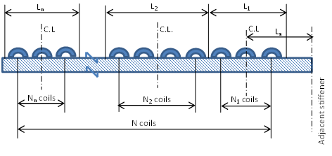
The combined cylindrical shell / half-pipe section is checked in accordance with paragraph 3.6.2.3 using as effective length of each group, Le, the value of the quantity Ln that is equal to the spacing between the centers of the coils at the ends of each group increased by one coil pitch (i.e. the spacing between the centers of two adjacent coils).
When calculating the quantity pys in accordance with paragraph 3.6.2.3, it shall be set A = 0. The area A is proportional to the stiffener cross-section times the ratio of the square of the shell mean radius to the square of the stiffener centroid radius. It follows that the standard requires to not take into account the additional contribution of the half-pipe cross-section.
The note 2 of the rule clarifies that in these calculations the effect of the pressure inside the half-pipe can be neglected [Author’s note: since it makes use of the area As not considered in computing pys].
The standard requires to develop the necessary considerations in those cases where the coil is interrupted (as it occurs in the vicinity of supports or nozzles).
The shell unsupported length, La, shall be equal to the distance between the centerlines of two adjacent stiffeners (which can also be two adjacent groups of coils).
As it is evident, the procedure of PD 5500 is more detailed than the one from EN 13445-3 and clarifies what this last leaves open.
This conclusion can be reached as long as it is noted that the equations used by EN 13445-3 for the light stiffeners are identical to those used by PD 5500.
The equation (3.11.3-7) of paragraph 3.11.4 provides the minimum required thickness for the portion of shell within a channel subject to the internal pressure Pc:
e = l ∙ √[Pc / (3 ∙ f)]
where:
-
l is the limpet coil attachment length measured on the outside surface (as shown in figure 3.11-3);
-
f is the cylinder design stress.
The note 1 clarifies that this formula is based upon the bending of a flat plate of length l, with the bending moment adjusted for the interaction between longitudinal bending and circumferential membrane loads. This approach leads to the same formula obtained assuming that the shell behaves as a beam of length l and unitary width, fixed at the ends (as it is proved by the factor 3) and bending stress limited to 1,5 times the design stress f.
The approach of PD 5500 is also described in the document ref. [4.] which is part of ref. [5.].
AD 2000 code requirements
The AD 2000 Code (ref. [6.]) permits the use of the half-pipe channels as stiffener rings against the external pressure acting on cylindrical shells. This subject is discussed in paragraph 7.4.2 of article B6 “Cylindrical shells subjected to external overpressure”.
This rule allows the use of either semi-circular (Figure 4) or square (Figure 5) channels.
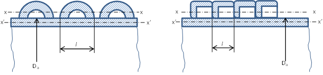 The calculation method is based on the calculation of the inertia moment and cross-section area with and without the channels. It needs therefore to compute the neutral axis x-x of the section with the channels.
Each channel is taken into account considering a length, l, equal to the outside diameter (half-pipe channels) or the external side length (square channels).
The ratio of the moment of inertia and cross-section area of reinforced to unreinforced sections is a factor that is introduced in equations (1) and (4) providing the allowable pressure against elastic and plastic buckling.
This approach provides credit to coils as reinforcing elements against the external pressure with no need to group them as required by PD 5500.
VSR and VSG Rules requirements
The Italian rules on pressure vessel construction, VSR Rules (ref. [7.]), deal with the channels welded on the outer surface of pressure vessels on chapter VSR.1.Q. This chapter provides the rules to evaluate the shell and the channel thickness. The channels may have different shapes: semi-circular, semi-elliptical, circular arc, rectangular or triangular. In this section nothing is said about the possibility to use these channels as reinforcing elements against the external pressure acting on a cylindrical shell.
The chapter VSR.1.H. provides the rules for the design of shells subjected to external pressure. The rule VSR.1.H.3 deals with the stiffening rings sizing and shows in Figure 1.H.3.1 some example of such rings. Also here nothing is said about the half-pipes welded to the external surface neither to permit, nor to prohibit to use them as stiffener rings.
The rule VSR1.Q.3 point 1. provides the equation (1.1) to evaluate the required thickness for the cylindrical shell to withstand the pressure P in the channels:
so = b ∙ √[P / (2 ∙ f ∙ z)]
where:
- b is the internal width of the channels;
- z is the efficiency modulus of the wall welding;
- f is the allowable stress of the shell.
In this equation the shell is assumed to behave as a beam of length b and unitary width, hinged (as proved by the factor 2) at the ends, and the bending stress is limited to 1,5 times the allowable stress f.
The VSG Rules (rif. [8.]) do not deal with these elements.
Additional information
A comprehensive discussion of pressure vessels behavior when subjected to external pressure is offered in the page “External Pressure” available in the PVEng website at the URL:
This discussion emphasizes that the shell which the half-pipe is welded to is not to be designed against an external pressure value equal to the inside pressure of half-pipes. The required shell thickness for this pressure is obtained with the equations of Appendix EE with no additional considerations.
Conclusions
Section VIII, Division 1, of the ASME Boiler and Pressure Vessel Code (BPVC) permits the use of the half-pipe heating / cooling channels welded to the outer surface of a cylindrical shell as stiffener elements against the external pressure.
Such use is allowed also by other international standards as EN 13445-3, PD 5500 e AD 2000.
Differently than PD 5500, ASME VIII-1 does not provide any specific rule on how taking into account, in calculations performed according to UG-29, fact that a portion of strength of the half-pipe is used to withstand the internal pressure and cannot be used for the stiffening function.
The author of this note considers that a possible approach consistent with the safety level required by ASME VIII-1 would consist in using, in the UG-29 equation providing the required moment of inertia of the combined (and not-combined) cross-section and in the calculation of the quantity A, the value of the half-pipe cross-section protion, A's, not used by the internal pressure. This value can be computed by deducting from the half-pipe nominal thickness, the required thickness computed with the equation (2) of the Appendix EE:
T = P1∙ r / (0.85 ∙ S1 – 0.6 ∙ P1)
where the symbols are the same as used in Appendix EE.
It is, however, recognized that ASME does not provide this indication and is underlined that it is here proposed by the author since he deems it reasonable on an engineering standpoint.
It is finally noted that neither EN 13445-3, nor AD-2000 provide a similar requirement; as well as these two standards do not adopt the same criterion as PD 5500 to split the coils into groups.


Add new comment